Research Article: 2022 Vol: 25 Issue: 2S
Modified Lips Region Extraction Method from Video for Automatic Lip Reading System
Ahmed K. Jheel, University of Babylon
Kadhim M. Hashim, University of Babylon
Citation Information: Jheel, A.K., & Hashim, K.M. (2022). Modified lips region extraction method from video for automatic lip reading system. Journal of Management Information and Decision Sciences, 25(S2), 1-16.
Keywords
Face Detection, Lip Localization, ROI Extraction, Frames, HSV Color Space
Abstract
Lip Reading is a visual means of communication. It relies on looking at the speaker's mouth; especially his lips to translate the speaker's words or sentences. The visual image (shape of mouth expression) and movement of lips make the visual recognition of speaking letters, words and phrases: gestures and expressions on the face. The location of the mouth and its extracted feature is important step to assist to better comprehend the visual speech. Researchers are constantly looking for innovative techniques to improve the effectiveness of lip. That is why this paper provides lip localization. Face recognition based on extraction technique from input video frames towards the segment of the mouth area. We'll be using an RGB & HSV color model, along with a adjust channels value, elliptical mask creation and use techniques to perform additional edge detection and morphological procedures.
Introduction
Lip-reading has developed in the past few years to become a major component of the Human-Computer Interface (HCI). The user no longer has to manually analyze speech. Meanwhile the performance of the automatic lip-reading system is easily affected by difficult conditions such as noise, light and low resolution.
Enormous advancement in the fields associated with developing computer capacity has contributed the system's robustness, making it more adapted to the real environment.
Lip is one of the prominent features of speech recognition because it is considered a major part of the face to get the visual information features; it has the advantages of fast calculation and high accuracy rate.
The lip-reading remains a powerful tool due to many advantages such as its low costs, the missing of physical contact between the user, and biometric systems.
Lip reading is one of the most challenging biometric techniques when unfolding in unrestricted environments due to the complete difference embodied by facial images in the real world (this type of facial portrait is usually designated as faces in violence).
Some of these variations include head poses, aging, occlusions, illumination conditions, and facial expressions. Examples of these are shown in Figure (1).

Figure 1: Typical Variations Found in Faces in-the-Wild. (a) Head Pose. (b) Age. (c) Illumination. (d) Facial Expression. (e) Occlusion.
Related Work
Coinaiz, et al., (1996) used HSV representation to highlight the red color which associated with the lips in the image. Later, the HSV color model is used for lip detection and locate the its position in mouth region. The boundaries of lips are extracted using color and edge information using a Markov Random Field (MRF) framework based on the lip area segmented.
Eveno, et al., (2001) proposed a new color mixture and (Chromatic transformation for lip segmentation. In this approach, a new method for conversion of the RGB color model and a chromatic map was performed to split the lips and facial skin under variable lighting conditions.
Later on Eveno, et al., (2004) introduced a novel method where the pseudo-hue was applied for lip localization that has been included in an active contour framework. the results show significant improvement in terms of accuracy in lip modeling.
Liew, et al., (2003) in those approach, they used new transformation method to convert given color image into the CIE-Lab color model and CIE-LUV color model, and then they calculated a lip membership map using the fuzzy clustering algorithm. The ROI around the mouth can be determined from the face area after a few morphological filters on an original image.
Namrata, (2015) in this way it was suggested that the image be converted from RGB color space to YCbCr and then decomposed into its components (luminance, blue chrominance and red chrominance) The Cb/Cr ratio was used to distinguish the face area. After that face image converted to HSV color space. Then on the cropped lip image of the lips edge detection and morphological operations were applied.
The Proposed Method
Feature extraction is preceded by an amount of preprocessing steps to be done in our method as shown in Figure (2). This includes face detection followed by (region of mouth extraction). Then, the lips of the speaker are respectively tracked in consecutive frames of recorded video. Following these steps, and given an instructive set of features, the visual module can proceed with feature extraction.

Figure 2: The General Diagram of Visual Feature Extraction
Pre-processing
When the video is received, the system decomposes the video into sequence of frames. All digital image processing techniques and proposed approaches are applied to these frames is implemented. Since each frame is individually processed. At first, Preprocessing is f required before feeding them to the face detector. There are some pre-processing techniques have been applied to each frame of the input video in border to decrease the computational complexity and fast obtain the face and lip features. As shown in Figure (3).
The pre-processing steps given by the following required operations before performing the proposed system:
Masked RGB Representation
The initial step in pre-processing stage is the color image representation. It should be implemented to highlight the object (speaker) in the frame. Then, the object should be isolated from the background image. Here, the color of the object is the main criteria for identifying the object.

Figure 3: The Main Steps to Implement Masked RGB Representation
Now, each frame will be converted into a color mask image that contains only the speaker and the background is false as shown in figure (3). Using certain thresholding functions by the Color Threshold Application, each color object can represent separately in the background. Each color will be having an upper range and lower range intensity value. That is mean the color space and minimum/maximum values for each channel of the image were automatically set by this application. The result in a binary mask BW and a composite image masked RGB image, figure (4) shows the original RGB image embedded with the mask BW. The algorithm (1) have been designated for this purpose.

Figure 4: Shows RGB Mask Creation
The above figure illustrates the main steps to implement RGB masked image for all frames of the input video. At first divide the input video into frames (frame rate 30 frames per second). On each frame, all the next steps are implemented on it. Converting the sequenced frames to a simple transformation that converts a color image (RGB) color model to an HSV color model, extract HSV (hue, saturation, value ) channels for all frames, define thresholds for each channel (H, S, V) based on histogram setting. The output masked image based on the input image. The last step set background pixels to zero.
| Algorithm(1) Create Masked Image |
| Input: |
| Video//that contains only one frontal face its 'size must be |
| Smaller than frame size. |
| Output: |
| The sequence of Masked RGB frames |
| Begin loop |
| Step1: Divide the original video into sequence of 30 (RGB) frames |
| Step 2: Convert RGB frame to HSV color space. |
| Step3: Define thresholds for Red channel based on the histogram setting. |
| Step4: Define thresholds for Green channel based on histogram setting. |
| Step5: Define thresholds for Blue channel based on histogram setting. |
| Step6: Create mask (BW) based on chosen histogram thresholds, these histogram thresholds are chosen using Color Threshold Application |
| Step7: Initialize output masked image based on the input image (RGB). |
| Step8: Set background pixels where BW are false to zero. |
| End loop |
| End Algorithm |
RGB TO HSV Conversion
This algorithm has been applied to sequence of RGB mask frames in order to obtain HSV mask frame (Figure 5). The HSV, or HSB, model describes colors in terms of hue, saturation, and value (brightness). The advantages of using hue are:
• The relationship between tones around the color circle is easily identified
• Shades, tints, and tones can be generated easily without affecting the hue
The advantage of HSV can each of its attributes corresponds directly to the basic color concepts, which makes it conceptually simple. The perceived disadvantage of HSV is that the saturation attribute corresponds to tinting, so de-saturated colors have increasing total intensity.
To convert RGB to HSV color space, the following steps should be followed taking into account the equations explained in the section ( )

Figure 5: Illustrate RGB to HSV Conversion
The above figure summarizes the process of converting the image into a color space after modifying the image components so that firstly convert RGB image to HSV color space using equations explained in section () . Then Extract each channel (hue, saturation, value) separately. Adjustment the value of the (hue, saturation, value) channels to be more appropriate to the conditions of ALU system. This adjustment can be done by multiply them by selective factors that affect the accuracy of the system.
| Algorithm (2): Pre-Processing/RGB to HSV Conversion |
| Input: |
| The sequence of masked RGB frames |
| Output: |
| The sequence of masked HSV frames |
| Begin |
| Step1: Convert all frame from RGB to HSV color representation |
| Step2: Extract HSV (hue, saturation , value ) channels for each Frame. |
| Step3: Adjust the values (hue, saturation, value)by multiplying by some of factors. |
| Step4: Recombine new hue, saturation, and value channels. |
| Step5: Re-convert HSV color model to RGB color model. |
| End Algorithm |
Note these set of factors are not fixed for all videos, but is approved by changing them according to the conditions of the video that you are working on. Recombine new hue, saturation, and value channels. Finally, convert again to RGB color space, as shown in figure (6). An algorithm is designated for this process as shown below.

Figure 6: Shows RGB to HSV Conversion
Face Detection
To build the face detector, here need to extract the face region only from each frame. To do that, the face has been detected by the following stages:
Binarization
Image binarization is very useful to detect the region of face. For all pixels in the masked RGB frame, where the background is zero and the ROI is solid. If the masked RGB frame pixels are not equal to zero then the new binary image is set to 1, otherwise new binary image set to zero as shown in figure (7). Now, as a result, the binary image had been created which have pixels are equal to zero. In other words, if I(x, y) represent the masked HSV image then the resulted binary image g(x, y) is given by:

Figure 7: HSV to Binary Mask
Elliptical Mask Representation
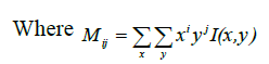
Whenever the speakers are detected in the frames an ellipse will be drawn for the face region, that ellipse will represent the boundary lines of the face of speaker. The next is step is need to find out the centroid of the object. For identifying the coordinates of the centroid. Should be find the image moments. Image an image moment is a certain a particular weighted average of the image pixels' intensities. Let the image moment inside the ellipse shape be Mathen the coordinates of the centroid can be calculated as follows:
• Area (for binary images) or sum of grey level (for greytone images):
• Centroid: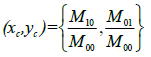
Once the centroid points are obtained this centroid point will be representing the center of face. The bounding ellipse can be put for the face region with respect to the centroid. The dimensions of the bounding ellipse can be obtained from the face region using the function region prop. Elliptical representation (as a semi-overlapping subdivision of the target) that incorporates both global and local target information in a single model can be used depending on some geometrical features such as the position of the centroid, the length of the axes, and the rotation angle are part of the target state. A set of geometric features are extracted based on the distances from length the vertical and horizontal centroid axes. Where enhanced face frames can be identified as the interior middle region from the face detection.
This area representation is effective for a limited application, but it is necessarily effective on a universal target.
Ellipse approximation had been modified as follow:
a- Create an elliptical shape on sequenced frames that contains only one frontal face its 'size must be smaller than frame size.
b- Define ellipse shape and its coordinates that is mean just a three-element specifies the initial location of the ellipse in terms of a bounding ellipse. The position has the form [center, minor axis length, major axis length]. The center of ellipse is qualifying to centroid of the white region that has been calculated.
c- Create a binary image ''mask" from the ROI: This section explains the production of an elliptical mask. The elliptical mask is sometimes referred to a white area in binary image. The procedure involves two stages. The first phase is horizontally locating the first intensity pixel value with 255 (from left to right and right to left) and the second phase is vertically locating the first intensity values with 255 (from top to down, and down to top ). Finally, the pixel values between horizontal and vertical result that had been located refer to as the ellipse mask. This operation diagram presents in Figure (8) returns a binary image that is the same size as the input image with 1s inside the ROI object h and 0s everywhere else. The input image must be contained within the same axes as the ROI
d- Calculate major &minor axes for ellipsed shape
e- Ellipsed portion cropped out.
f- Burn elliptical binary mask in the original image: it means the logic operations AND and OR are used to combine the information in two images. This may be done for special effects, but a more useful application for image analysis is to perform a masking operation. AND and OR can be used as a simple method to extract an ROI from an image. For example, a white mask AND with an image will allow only the port on of the image coincident with the mask to appear in the output image, with the background turned black; nandia black mask OR with an image will allow only the part of the image corresponding to then black mask to appear in the output image, but will turn the rest of the image white. This process is called image masking and Figure (8) illustrates the results of these operations.

Figure 8: Elliptical Face Creation
| Algorithm(3): Face Detection for Each Frame |
| Input: |
| Sequence of frames |
| Output: |
| The sequence of Ellipsed face images |
| Begin |
| Loop: from 1 to the no. of the frames |
| Step1: Create a draggable elliptical shape on frame its position smaller than frame size. |
| Step2: Specify a position constraint to keep the ellipse inside the original xlim and ylim ranges |
| Step2: Define ellipse shape and its coordinates //after Specifies the initial location of the ellipse |
| [x y width heigh] |
| Step3: Create a binary image ("mask") from the ROI face. |
| Step4: Burn elliptical binary mask in the original image |
| //images multiplication (pixel by pixel) |
| Step5: Calculate major &minor axes for ellipsed shape |
| Step6: Ellipsed portion cropped out |
| Next |
| End Algorithm |
Lip Detection\Localization
The lip detection is to determine the approximate location of the input image, which is very important stage in lip reading system. Early lip localization research usually uses a camera attached to the human face. It was now extremely sophisticated, primarily skin color model, self-face model, template model, and other methods. The following technique was used to introduce ROI (Gong, 1995; Jian et al., 2012; Ruwei, 2012).
Region of Interest Extraction
Region of Interest (ROI) extraction of mouth area is a crucial step in automatic biometric system. The recognition process depends firstly on the accuracy degree of (ROI) extraction process. This stage is useful to reduce the computational complexity and speed up the processing time when searching for lip component regions.
The aims of this step are to specify the real region in the image and to discard the region containing unnecessary information in the image.
The ROI representing the mouth region where the lip edge is located. To avoid the recognition of false features. The segmentation of ROI IS mainly necessary.
The below figure (9) shows how to get the region of interest by making some segmentation on the burned face area with the ellipse-shaped mask.
At first need to divide the width of the shape into four parts using straight imaginary lines and divide the length into three thirds in the same way that will form specified area at the bottom of the face represented by coordinates

Which is calculated to?

Figure 9: Region of Interest Extracted Using the Ellipse
The focus of this dissertation is to hold the lip segment as a region of interest. To reduce redundant information, it is unnecessary to next extract the mouth area.
In previous studies, researchers have proposed a variety of methods to extract lip area. However, these methods still contain redundant information or harm the subsequent processing. In this section, geometrical method has been suggested that can segment the face area according to the general structure and proportion of the face. The formula that used as follows:
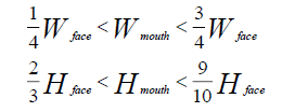
Where Wface and Hface are the width and height of the face and Wmouth and Hmouth are the width and height of the mouth region. From the formula ( ), the mouth region can be obtained as shown in Fig. (9). It explains those method can get satisfactory and effective results in the proposed system
| Algorithm(4): Lip Segmentation |
| Input: |
| Sequenced of the Ellipsed face image |
| Output: |
| Mouth region for each frame |
| Begin |
| For i= 1 to no. of frame |
| Step1: Divide the Ellipsed face image into four vertical stripes of |
| equal width equal to Wface /4. //Wfac =minor length of an |
| ellipse. see figure() |
| Step2: Divide the Ellipsed face image into an equal three |
| horizontal stripes, of the height equal to Hface /3. |
| // Hface= major length of an ellipse. see figure(1-6/e) |
| Step3: make across between the vertical and horizontal strips |
| Step4: Specify 4- a point that determines the last portion of the |
| the ellipse that can fit conveniently into the mouth region |
| Step5: From step(4), form a rectangular shape that exactly |
| corresponds to the mouth region. |
| Step6: mouth region cropped out. |
| endfor |
| End Algorithm |
This algorithm was applied on a set of single images and provided a good result for those images, and applied on sequence of frames as shown in figure (10). This is an early step to extract visual features from the ROI image. Furthermore, when the ROI is determined, there is need to decrease the amount of data that undergo consequent processes by forming out the bounding box of ROI from the image. To obtain the most accurate results, before features extraction step needs to enhance the cropped image.
Region of Interest Enhancement
Image enhancement is one of the most important techniques in image processing. To understand and analyze the images, various image enhancement techniques are used. To improve the cropped frame. Firstly, noise is reduced using the median filter because it is effective to remove the noise that occurs during the shooting process in addition to its advantage in preserving the edges, then histogram equalization technique is used to provide a better quality of images without loss of any information. Finally, contrast stretching techniques are used to increase the visualization in image structures of the parts light and dark at the same time.
Median Filter
The median filter is applied to all frames due to its have good behavior to reduce some limited noise types such as “Gaussian,” “random,” and “salt and pepper” from (an image and signal) with its properties to preserving edge]. In the mechanism of the median filter, the center pixel of an M × M neighborhood is replaced by the median value of the corresponding image portion. Using this idea median filter can remove this type of noise problem (Kumar et al., 2012).
The median of observations Xi, i = 1, .. , is denoted by med (xi) and it is given by:
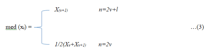
Where x (i) denotes the order statistic. In the following, mainly the definition for an odd n can be utilized.
A one-dimensional median filter of size i= 2v+i1 is defined by the following input-output relation:

Its input is the sequence xi , i Z and its output is the sequence yi , i Z. is also called moving median or running median.
A two-dimensional median filter has the following definition:

The set A Z2 defines a neighborhood of the central pixel (i, j) and it is called the filter or window. Median filtering is yet another must-have feature because not only it renders the image/text documents more comprehensible but it also enhances OCR results if applied before OCR submission.
Histogram Equalization
As previously mentioned, the histogram equalization essentially extends intensity values along with the entire range of values to create more contrast. This technique is particularly helpful when an image is represented by close contrast values such as images that both the background and the foreground are simultaneously bright, or both are dark at the same times, In this section, the general technique for cumulative histogram equalization is described. Here are the steps for implementing this technique (Rafael, 2012).
• Create the histogram for the image.
• Calculate the cumulative distribution function histogram.
• Calculate the new values through the general histogram equalization formula.
• Assign new values for each gray value in the image.
Contrast Stretching
It is one of the common degradations in the video frames captured. The contrast between the highest and the lowest intensity values of a picture may be determined. Contrast enhancement makes it simpler to understand frames by making it easier to identify object characteristics. The aim of that image enhancement technique is to adjust the intensity of illumination to be clearly differentia for human viewers.
The resultant image after a stretching of contrast is better than a deformed image, since it firstly made it possible to see image features in areas which were either extremely bright or very dark.
Secondly, to modify each image element value to enhance visualization in the darker and brighter parts of the image at the same time (Sahidan et al., 2008).
The contrast is stretched via a window (named then KERNEL) and the center element is adjusted using the formula (Attas et al., 1995):

Where (x, y) are the coordinates of the center picture element in the KERNEL, and Imin & Imax are the minimum and maximum intensity values of the image data in the selected KERNEL.
Canny Edge Detection
Edge detection is an essential method for extracting structural information and significantly lowers the quantity of data to be analyzed. Canny edge detector attempts to satisfy three general edge detection criteria.
1. Low error rate, which implies that only existing edges are detected.
2. Good localization must be reduced the difference between actual edge pixels and the identified edge pixels.
3. The detected edge should only be indicated once, not multiple times. The procedures for detecting the Canny rim are illustrated in the figure (10)

Figure 10: Canny Edge Detection Process
Region Props
Even with optimum mouth filters, the filtered picture sometimes includes undesirable tiny regions. A typical case is seen in Figure (11) where the shadow beneath the chin is not sufficiently sure to differentiate it from the lips. In order to minimize the effect of these events, an area of interest (ROI) must be extracted from the picture produced in the previous section. This is done via the use of vertical and horizontal picture signatures. Every signature is a vector holding pixel value sums for a certain row or column. The borders of ROI may be identified by looking in each vector for elevation and descent. Although the tiny regions are large enough to show on the image signatures, it may be eliminated if it is size less than 50. Only the portion inside the ROI of the filtered image was further processed.
Here, all the areas in the binary image were measured in addition to the ID pixels list. After that, the largest area among the group of areas was chosen as the upper and lower lip area as one area, then select the second largest area among the remaining areas to represent the area of the gap formed when the mouth is opened. Regarding the selection of the second-largest district, this was done with the following steps that have been taken into consideration after choosing the first largest area from the group of regions.
| Algorithm(5): Regionprops |
| Input: |
| Sequenced of frames |
| Output: |
| Pure lip region |
| Begin |
| For i= 1 to no. of frame |
| Step1: Determine the number of regions in the mouth region and the set ID for each region. |
| Step2: Sort all regions in descending order. |
| Step3: Select the maximum region that corresponds to the first region. |
| Step4: Create new list include regions that satisfy the condition if it is less than the maximum region, then put it in a new list and so on. |
| Step5: Sort new list in descending order. |
| Step6: Find the maximum regions that consider the second largest area. |
| Step7: Show the maximum area that obtained from the original an new list. |
| Step8: False the remaining regions. |
| End for |
| End Algorithm |
Notes through the new list that contains all areas except the first largest area, the largest area can be selected again, which represents the second-largest area in the list from step 2. Now there is two areas that need to have appeared, each of these areas has its index that can be used as a parameter in the Pixel ID list. To make the image black by setting the value of each pixel to zero and then appear the pixel ID that holds that index.
Result
140 videos were received from AVletters2 Dataset each video contains only frontal person who pronounces 5 English vowel letter 7 times in each of them consisting of 24-48 frames per second photographed by camera with
1920 × 1080 resolution a proposed system have been applied to them, good results were obtained. Looking at the poor lighting at the beginning of the algorithm, we converted the RGB model to HSV color model we adjusted the value of hue, saturation and then recombined after that re-convert HSV model to RGB model. To improve the image, first, we reduced noise using the median filter because it is effective to remove the noise that occurs during the shooting process in addition to its advantage in preserving the edges, then we equalized histogram to provide better quality of images without loss of any information.
Then contrast stretching techniques are used to increase the visualization in image structures of the parts light and dark at the same time. A binarization method is further applied on the enhanced frames to segment the lips. Morphological operators can be used, region prop the binary image as shown in Figure (12). Using Lip region Extraction Algorithm , extracted Vise me for. Five different classes are tested in this algorithm for many frames for each speaker. On an average are getting 97% results for all speakers.

Figure 11: Illustrate Back Ground Isolation and HSV Color Space Algorithm from Some Sample of Data Set

Figure 12: Illustrate Back Ground Isolation and HSV Color Space Algorithm From Some Sample of Data Set
Conclusion
After completing the implementation of this algorithm, we were able to obtain the lip localization for the purpose of extracting features that in turn are of high accuracy for any available dataset, and this method can be worked on in the future in real-time applications. Note that we were able to extract many of the strong features (such as canny detector, surf descriptor, width and height of mouth) for the purpose of speech recognition and this was in our next scientific research.
References
Coianiz, T., Torresani, L., & Caprile, B. (1996). 2D deformable models for visual speech analysis. Proceedings of Springer, Speech reading by Humans and Machines, NY.
Crossref, GoogleScholar, Indexed at
Eveno, N., Caplier, A., & Coulon, P.Y. (2001). A new color transformation for lips segmentation. Proceedings of IEEE Fourth Workshop Multi- media Signal, 3-8, Cannes, France.
Crossref, GoogleScholar, Indexed at
Eveno, N., Caplier, A., & Coulon, P. (2004). Accurate and quasi-automatic lip tracking. Proceedings of IEEE Transactions on Circuits and Systems for Video Technology, 14(5), 706-715.
Crossref, GoogleScholar, Indexed at
Liew, A.W.C., Leung, S.H., & Lau, W.H. (2003). Segmentation of color lip images by spatial fuzzy clustering. Proceedings of IEEE Transactions on Fuzzy Systems, 11(4), 542-549.
Crossref, GoogleScholar, Indexed at
Namrata, D. (2015). A lip localization based visual feature extraction method. Proceedings of an International Journal Electrical and Computer Engineering, 4.
Priyanka, P.K., & Bharkad, S.D. (2019). Lip feature extraction and movement recognition methods: A Review. International Journal of Scientific & Technology Research, 8(8).
Gong, Y. (1995). Speech recognition in noisy environments: A survey. Speech Communication, 16, 261–291.
Crossref, GoogleScholar, Indexed at
Jian, L.I., Changkui, C.H.E.N.G., & Tianyan, J.I.A.N.G. (2012). Wavelet de-noising of partial discharge signals based on genetic adaptive threshold estimation. IEEE Transactions on Dielectrics and Electrical Insulation, 19(20), 543-549.
Crossref, GoogleScholar, Indexed at
Ruwei, L.I., Changchun, B.A.O., & Bingyin, X.I.A. (2012). Speech enhancement using the combination of adaptive wavelet threshold and spectral subtraction based on wavelet packet decomposition. ICSP 2012 Proceedings, 481-484.
Crossref, GoogleScholar, Indexed at
Dave, N., & Patel, N.M. (2014). Phone me and vise me based approach for lip synchronization. International Journal of Signal Processing, Image Processing and Pattern Recognition, 7(3), 385-394.
Vinod, K., Priyanka, D., & Kaushal, K. (2012). A hybrid filter for image enhancement. International Journal of Image Processing and Vision Sciences (IJIPVS), 1(1).
Rafael, C.G., & Rechard E.W. (2021). Digital image processing, (3rd edition). Pearson Education International, 144-147.
Sahidan, S.I., Mashor, M.Y., Wahab, A.S.W., Salleh, Z., & Jaafar, H. (2008). Local and global contrast stretching for color contrast enhancement on ziehl-neelsen tissue section slide images. Biomed Proceedings 21, 583–586.
Attas, I., Louis, J., & Belward, J. (1995). A variational approach to the radiometric enhancement of digital imagery. IEEE Transactions on Image Processing, 4(6), 845-849.
Received: 25-Nov-2021, Manuscript No. JMIDS-21-8331; Editor assigned: 27-Nov-2021, PreQC No. JMIDS-21-8331 (PQ); Reviewed: 01-Dec-2021, QC No. JMIDS-21-8331; Revised: 05-Dec-2022, Manuscript No. JMIDS-21-8331 (R); Published: 05-Jan-2022